Some of Bob's Electronic Projects
Submitted for your approval.......
The Pocket Tesla Coil.
This is not a true Tesla coil, but it is a high voltage, high frequency oscillator. As I recall, I built this around 1970.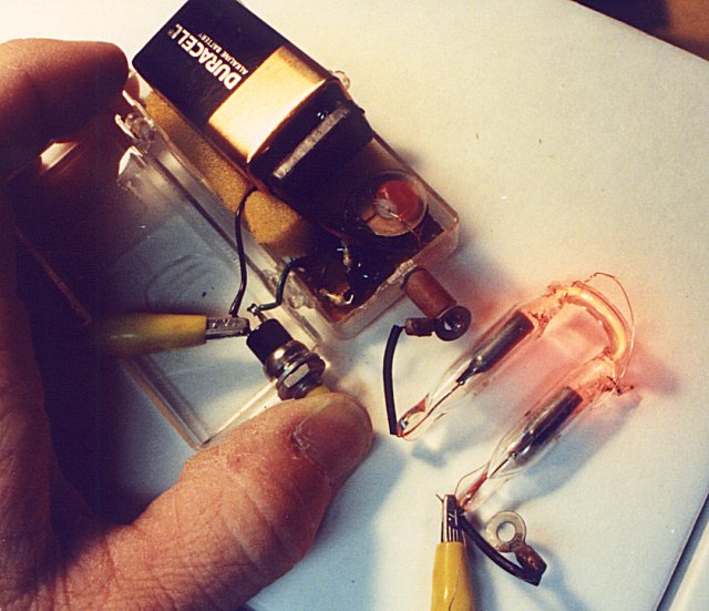
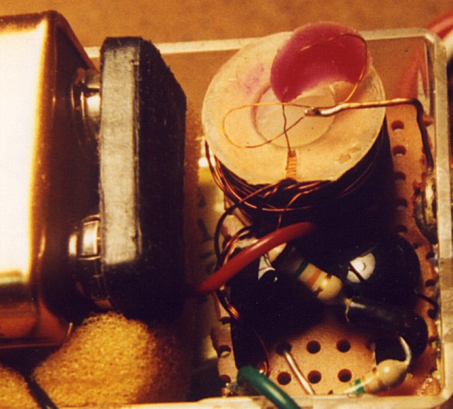
The circuit consists of two 2N3638 transistors in a push-pull oscillator configuration. The coil is from a toroid inductor (I'm guessing about 100mH) which was taken from an old pay TV converter I bought from Meshna Surplus (remember them?). This was about 30 years ago, and I think that I wound about a 30 turns of #28 wire, center tapped for the primary, and the base of each transistor connects to the collector of the other through a 15K resistor to provide bias and feedback. It runs off a 9 volt battery. A project like this looks harmless enough, but it puts out about 950 volts at 850 KHz. At that frequency, the danger isn't so much shock, but it will produce an RF burn if the output lead is touched. The next picture is a close-up of the coil.
In the first picture, the coil is shown lighting a neon indicator. I wrapped a thin wire around the tube to get it started. This coil will also light the larger neon bulbs the same way that those high-voltage globes at Radio Shack work, except that the neon lights up where your fingers touch the glass. It can also be used to light fluorescent tubes. Once, I used it to light a tube so I could see to put it in the fixture.
Here's a neat experiment you can do on a dry, cold night. Grab hold of a 15 inch or so fluorescent tube in a dark room, and scuff your feet on the floor. Wearing socks on a linoleum floor works very well. Touch the other end of the tube to a water faucet (or other grounded metal), and watch the tube flash.
Not shown here is another project in a similar vein. This one is built like the Pocket Tesla coil, except that it is built on a color TV flyback transformer, and uses a lot more power. This coil will generate about 30KV, so it's just as dangerous as reaching inside a TV set. Not recommended for beginners. When a standard clear globe light bulb is hooked up to it, it will arc like the Radio Shack globe, but it will produce a nasty shock.
So much for the fun stuff.....
The Music Composer
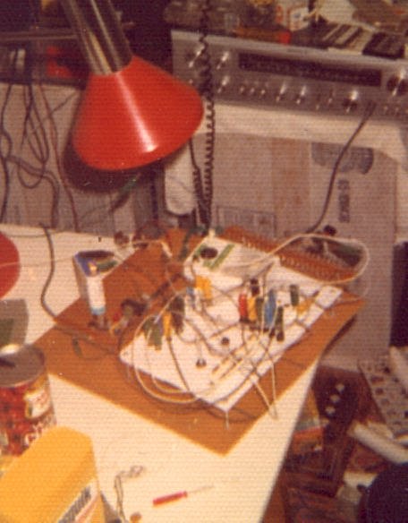
One day while I was stationed in Germany, Bruce mentioned to me that people were making musical composers by stringing up counter chains, and feeding the output to a voltage controlled oscillator (VCO). From that description, I built one. The photo isn't too awful good - it was taken with a really cheap camers.
Here's a diagram of how it's set up:
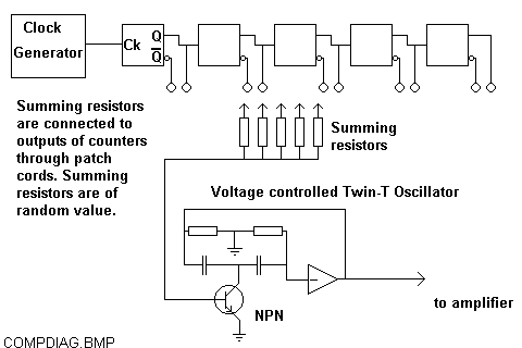
The clock generator sets the rate at which the counter chain advances. The summing resistors
are connected to the outputs of the counters, which results in different currents going into
the base of the NPN transistor. The transistor forms the resistive element of the lower "T"
network of the Twin-T oscillator. The result is random music. It must be kept in mind that the
tunes which a unit like this will produce are not chromatic - they don't follow our Western
musical scale, but they are very interesting. If you are wondering how musical a machine like
this could be, listen to "And You And Me" by the group Yes. The melody of the song is
structured just like the binary sequences that a composer produces, and I wouldn't be
surprised a bit if Yes used a composer to inspire the song.
Several oscillators may be combined (using their own summing networks). At one point, I had one oscillator doing a medlody, one producing a bass line, and also had a keyed white noise generator wired up.
You can get more sounds out of it by wiring up summing resistors directly to the amplifier, resulting in a click track. Use some capacitors to provide a different timbre to the clicks. I was also able to put some capacitors in series with the summing resistors on the VCO to get a portamento (sliding notes).
Probably the worst thing you can do to a project like this is to put it in a box. It's whole purpose is to be flexible, and once it's tied down, it becomes rather useless. A good breadboard project.
In the northwest corner of the composer is the perf-board which has the counters, and two VCO's
are visible next to the battery (black & green clipleads) which powers it. The thing that
looks like a white transistor radio used to be a white transistor radio. It has been hollowed
out, and it contains the clock generator which sets the tempo of the music. The white area is
where the patch cords go, along with the clip leads for the additional sound producing
circuits. Not bad for something built in a German Gasthaus.
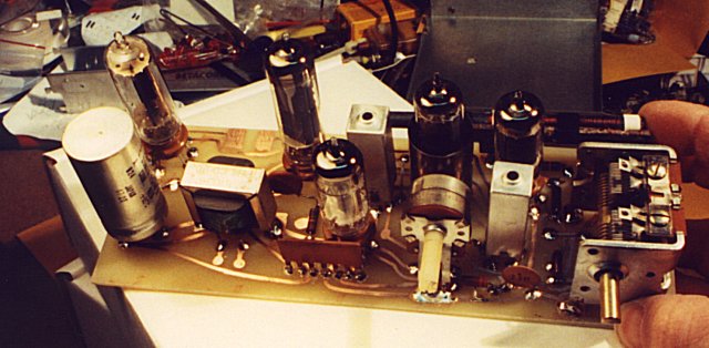
The PAIA Synthesizer
Like many other electonic music enthuiasts, I was very excited when PAIA offered the 2700 series synthesizer in 1973. This was many years before Casio and Yamaha brought out their portable keyboards, and the cheapest Moog was thousands of dollars. PAIA's synth was about $144. Of course it wasn't in the same class. The first units used shirt buttons and wire springs for a keyboard, and it was tuned by moving contact points on a conductive plastic strip, but it worked, and it was very flexible. When the 4700 series modules came out, I bought some, along with the new controller which used a high-quality Pratt & Reed keyboard, and a good quality resistive divider with trimpots.
As time went on, I added to the setup with more modules which I built from scratch. I also added a polyphonic synth which appeared in Radio-Electronics magazine. This was controlled by a keyboard, or the Heathkit ET3400 trainer. PC's were still in the $5000 range at the time.
This was a really neat setup, but then the Casio units came out. Much easier to use, no tuning problems, and they were polyphonic. The CZ-100 was a lot of fun also, and I built my first MIDI interface into a TRS-80 clone, and programmed it in BASIC.
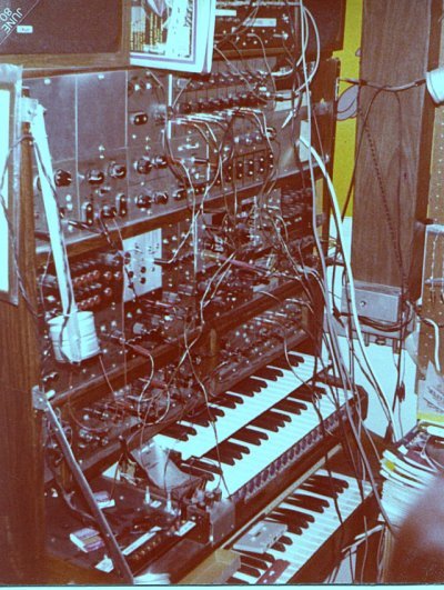
The picture shows the most advanced setup of the PAIA synth. On the top shelf are two speakers and a sequencer. The next few rows consist of PAIA modules, as well as some of my own design. The upper keyboard goes to the polyphonic synth, as well as the black control panel to the left. The middle keyboard is for the PAIA modules, and the bottom keyboard with all the junk collected on it is the keyboard for the Silvertone spinet organ, which the whole setup is sitting on (or is it setting on?). The vertical thingie in the wood grain vinyl on the right side of the picture is a Hammond reverb, which has the support springs immersed in oil. This synth is long-gone (sold), but I have a few tapes I made from it. I'll add some wave files later.
This is a scan of a Polaroid (yes, I used to have one of those...) of the polyphonic synth. This
unit was based on a string of 49 CA3080 transconductance amps. It worked pretty well, but not
as well as the portable units. At the left of the photo are the reed relays which adapted the
comnputer output ports to the PWM attack/decay lines going to the keyboard.
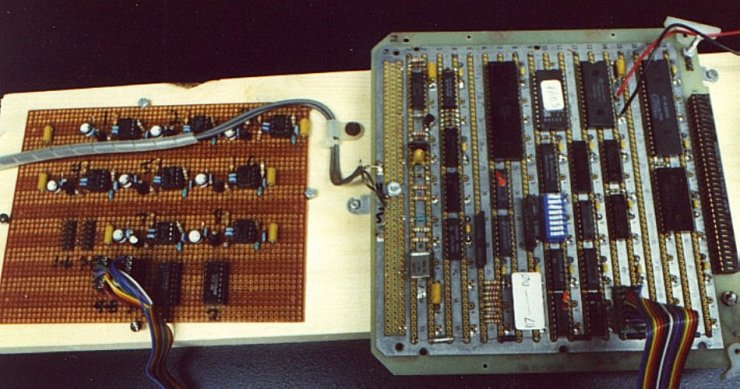
The NotePicker
Be sure to prounounce that correctly
The purpose of this thing is to capture a few seconds of music, and play back a selected
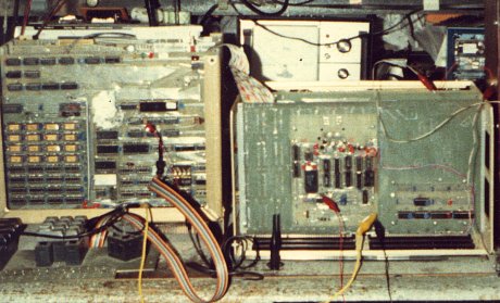
portion repeatedly, so that the notes can be picked out. The photo shows the PC boards, before
any packaging was done. It's basically a Z80 memory board, but with an additional 4 bits tacked
onto it to make it 48K by 12 bits. Memory was still very expensive at the time. The RAM data
bus was separated from the CPU, which served as a memory controller. The data bus was
connected to a 12 bit A/D converter, and a 12 bit DAC. About 12 seconds of audio could be
recorded, and the start and end times could be manipulated individually or together. The result
was as if having a tape loop which could be adjusted on the fly, down to about 1 millisecond.
There is a Notepicker 2, but it's about to be replaced with Notepicker 3.
The Capacitor Bank
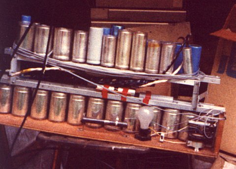
This started out as a small collection, but grew to 330,000 MFD at 50 volts. That's enough energy to get a 12 amp Shop Vac going. But you may ask what's it for? To make sparks. BIG sparks. Not shown in the picture are the aluminum bars which were chewed up by the huge amounts of current generated when verious pieces of metal were placed across them. The sound was just like a firecracker. The best results were gotten when some magnesium blocks were shorted on it. The magnesium oxide provided a deeper sounding boom. This thing will leave two rows of perforations on a beer can in one loud snap. Very dangerous with all those sparks flying. Set the grass on fire one day. Not recommended for beginners.
The large power resistor is for current limiting while charging, and the light bulb is for discharging. This project was taken apart a few years ago. Seems that the newer capacitors available today can give me more energy, and they'll take up less room than a shoe box.....
LED Scope
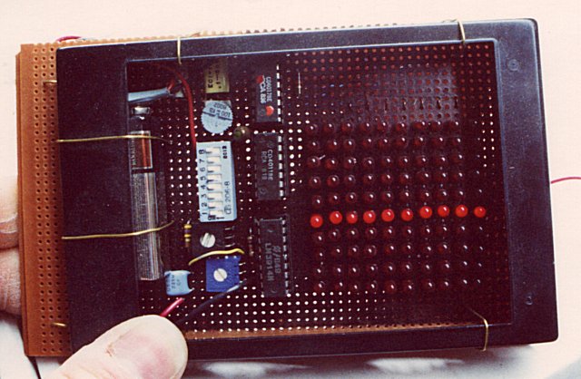
This scope was described in one of the project books from Radio Shack, by Forrest H. Mims. The photo shows the scope displaying a baseline. I shoud have run a signal through it. It does have enough resolution to display the difference between a square wave, a sine wave, or a triangle wave. This one is built (mostly) inside a Polaroid film case.
Surface Mount Radio
When the company decided to go with SMT, I took apart an old radio with a PC board, reversed the traces, and etched a board. I then soldered the parts on it, SMT style. It works. Not very stable, but it works.
Drum Pad Controller
Just like the Sony Walkman, I had to build a drum set before I could justify buying one.
When I was playing with the band, I wanted a drum set, but why buy it if I could build it? This
project uses a Z80 which polled the drumpad request FF's, and sent out a MIDI message to my
Roland TR626. It worked really good. The biggest problem was coming up with a durable, but
sensitive pad design. I wound up using a square piece of PB board material with a small
beeper speaker fastened to it. The pads were covered with two thicknesses of bath towels to
cut down on the mechanical click sound, yet leave it sensitive enough to detect the stick
hitting it. The photo shows the signal conditioning board, and the Z80 board with the serial
converter.
Front page