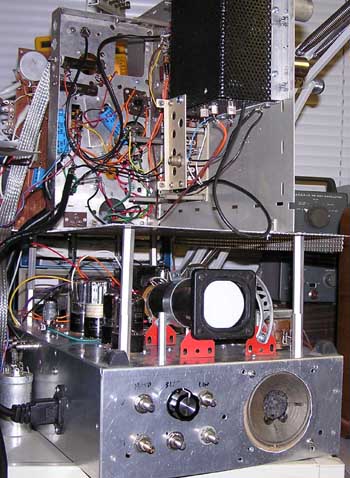
The 2AP1 CRT is mounted to the bottom chassis which contains the sync & sweep circuits,
along with the HV supply which was lifted from a 3 inch Heathkit scope. The extra HV is needed
because a full raster needs more voltage than a single trace to get a decent picture.
Also on the chassis is the audio amplifier.
Upstairs, in the perforated black box is the tuner. Since broadcast TV is going away, I only
built up enough channels to receive a VCR modulator on 4, and local broadcast channels 3 & 5.
The two knobs are channel select and fine tuning.
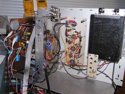
The IF strip is just behind the tuner, and the vertical chassis with the two blue electrolytics
is the B+ supply for everything but the audio.
Beyond that chassis is a piece of perf board with the video amp and the audio IF and detector.
The two DMMs in the background are the plate & screen meters for my Gm tester, based on the RAT tester
from Steve Bench.
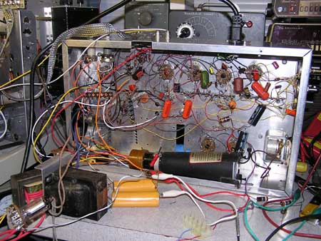
Here's a view of the underside of the sweep chassis before the audio, CRT and HV supply were installed.
The HV supply consists of the larger Heath transformer, a 1V2 rectifier, a Radio Shack filament
transformer with a new secondary made of test lead wire, and a couple of HV filter caps.
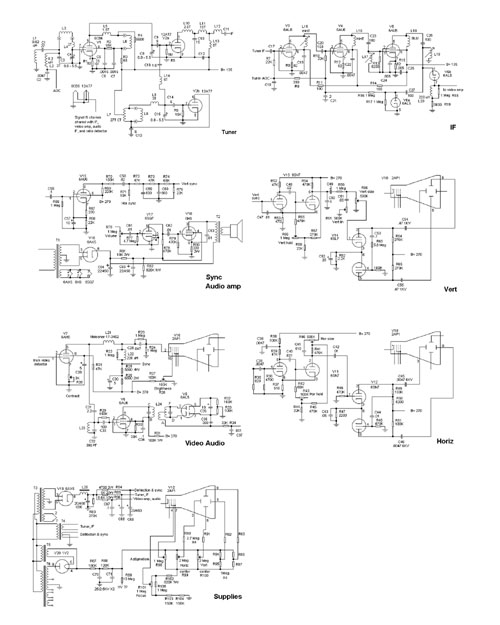
Here's a low-res image of the schematic. Standard stuff, except that I had to scale down the
deflection circuits for the 2AP1. Portions of the schematic were taken from other TV sets.
The tuner is from a Crosley set with an Inductuner. I wanted to be original, so I switched the coils instead of using the continuous inductor. Also, if I wanted to build it as a single channel set, I could eliminate the channel switch.
The IF strip is from an old Meck TV which was inhabited. Really, by mice. It would have been a great restoration project except for the rodent-induced rust, the foul odor, and the chewed wires. The lady who sold it said that it would be worth $500 (maybe in Monopoly money). On top of that, some of the tubes were missing or in the wrong place, and the HV rectifier socket was removed. The tuner was a two-band type with a variable capacitor. The channel dial would increment as the knob was turned clockwise, then when the capacitor was at minimum capacity, the band switch would flip, and flip the dial, which picked up at Channel 13, then back down as the capacitor went back to maximum capacity.
The video amplifier, audio IF and ratio detector were taken from the 21" TV that dad got with his DeForest's home training course. That set was huge, and the CRT was 70 degrees, which made it about three feet long, it seems. We didn't have lots of money in those days (around 1958), so dad built a console cabinet out of Masonite.
The audio amp is a run-of-the-mill 6SQ7 and 6K6 two stage affair. It has it's own power transformer because the B+ winding on the main transformer was too close to it's limit.
The sync and deflection circuits are from an old Tele-Tone portable TV using a 7JP4.
The power supplies are standard, and the CRT circuitry was designed around the 2AP1 spec sheet.